Linux 网络设备
概述
参考:
脚注在文末
Linux 网络设备归属于 PCI 总线类型。
关联文件
sysfs 中的网络设备信息
每个网络设备,都会在 sysfs 中注册(主要是与 PCI 相关),有一系列文件用来描述或定义这些网络设备。
在 /sys/class/net/${NetDeviceName}/ 目录下可以找到已在内核注册的关于网络设备的信息
Note:
${NetDeviceName}是指向/sys/devices/pciXXX/XXX/.../XXX/${NetDeviceName}/的 Symbolic link
./type # 网络设备的类型。文件内容是 10 进制数字。从 if_arp.h1 代码中(stackoverflow 也有相关问题)找到数字对应的设备类型表和该设备的定义(e.g. 1 表示 ARPHRD_ETHER),这个 C 的头文件将网络设备分为如下几大块
- ARP 协议硬件定义 # ARP 的 RFC 标准中,定义了这些,并且 IANA2 中也维护了这些注册信息。
- 比如
#define ARPHRD_ETHER 1这行代码意味着,type 文件的内容为 1 的话,表示该网络设备是 ARPHRD_ETHER(也就是常见的网卡设备)
- 比如
- 非 ARP 硬件的虚拟网络设备 # Linux 自身实现的一些虚拟网络设备
- TODO: 其他信息待整理
./flags # 网络设备的 Flags(标志)。文件内容是 16 进制数字。常用来描述设备的状态和基本功能。Linux 内核文档中的 ABI 部分提到了可以从 if.h3 代码中 enum net_device_flags 这部分及之下的内容,找到这些 Flags 的含义。代码中的含义与 flags 文件中的 16 进制数字应该如何理解详见下文 flags 文件详解
- Notes: ip 程序的 link 和 address 子命令通过 show 显示的网络设备信息中,第三部分由
< >包裹起来的就是网络设备的 Flags - stackoverflow 可以找到相关提问
./carrier # 网络设备的物理链路状态。0 表示 down;1 表示 up
./carrier_changes # 网络设备的物理链路状态变化的次数,从 up 变为 down 以及 从 down 变为 up 的总次数。
./device/ # PCI 设备资源信息(包括设备供应商、设备类别、etc.),该目录是 /sys/devices/pciXXXX:XX/.../XXX 下的 PCI 相关目录的软链接,可以从 PCI 文章中查看各文件的含义。
- ./uevent # 用户空间事件,物理机中该文件中包含 网络设备的驱动与 PCI 信息。
- PCI_SLOT_NAME # 网络设备所在的总线信息,与 ethtool 命令的 -i 选项输出的 bus-info 信息相同;与 lspci 的第一列信息相同;与
lshw -C net -businfo的第一列信息相同- Notes: 虚拟机中,该文件没有 PCI_SLOT_NAME 的信息。
- https://stackoverflow.com/questions/78497110/how-to-get-bus-info-in-a-generic-way
- https://askubuntu.com/questions/654820/how-to-find-pci-address-of-an-ethernet-interface
- https://stackoverflow.com/questions/73650069/how-to-use-ethtool-drvinfo-to-collect-driver-information-for-a-network-interface
- 具体解释详见下文 通过 PCI 识别网络设备
- PCI_SLOT_NAME # 网络设备所在的总线信息,与 ethtool 命令的 -i 选项输出的 bus-info 信息相同;与 lspci 的第一列信息相同;与
- TODO: 其他信息待整理
~]# lshw -C net -businfo | grep I350
pci@0000:61:00.0  eno1       network        I350 Gigabit Network Connection
pci@0000:61:00.1  eno2       network        I350 Gigabit Network Connection
~]# lspci | grep I350
61:00.0 Ethernet controller: Intel Corporation I350 Gigabit Network Connection (rev 01)
61:00.1 Ethernet controller: Intel Corporation I350 Gigabit Network Connection (rev 01)
~]# ethtool -i eno1 | grep bus-info
bus-info: 0000:61:00.0
~]# cat /sys/class/net/eno1/device/uevent | grep PCI_SLOT_NAME
PCI_SLOT_NAME=0000:61:00.0
flags 文件详解
在 /sys/class/net/${NetDeviceName}/flags 文件中,通常是 16 进制的数字,e.g. 0x1303、0x1003。想要理解这些数字,需要配合 if.h3 代码中的内容才行,在代码中可以看到如下对 网络设备的 Flags 声明(源码中还有注释,解释了每个 Flag 的含义):
/* 声明了一个枚举类型 net_device_flags,为这些 Flags 定义了变量与数字的对应关系 */
enum net_device_flags {
/* for compatibility with glibc net/if.h */
    IFF_UP        = 1<<0,  /* sysfs */
    IFF_BROADCAST   = 1<<1,  /* volatile */
    IFF_DEBUG       = 1<<2,  /* sysfs */
    IFF_LOOPBACK   = 1<<3,  /* volatile */
    IFF_POINTOPOINT  = 1<<4,  /* volatile */
    IFF_NOTRAILERS  = 1<<5,  /* sysfs */
    IFF_RUNNING     = 1<<6,  /* volatile */
    IFF_NOARP       = 1<<7,  /* sysfs */
    IFF_PROMISC     = 1<<8,  /* sysfs */
    IFF_ALLMULTI   = 1<<9,  /* sysfs */
    IFF_MASTER     = 1<<10, /* volatile */
    IFF_SLAVE       = 1<<11, /* volatile */
    IFF_MULTICAST   = 1<<12, /* sysfs */
    IFF_PORTSEL     = 1<<13, /* sysfs */
    IFF_AUTOMEDIA   = 1<<14, /* sysfs */
    IFF_DYNAMIC     = 1<<15, /* sysfs */
    ......略
}
这些代码利用了 C 规范与标准库 的位移运算符以为每个 Flags 设置了一个在二进制形式下的标志位,比如:
- 1«0 表示二进制的 1,对应 IFF_UP
- 1«4 表示二进制的 10000,对应 IFF_POINTOPOINT
- 1«12 表示二进制的 1000000000000,对应 IFF_MULTICAST
- etc.
Notes: 所谓设置标志位,就是指通过位移让二进制形式的 1 出现在指定位,出现在第几位,第几位就表示某个特定的含义,比如上面 IFF_BROADCAST 1«1 表示移动了 1 位,那就说明在第 2 位的数字用来表示 IFF_BROADCAST。由于每个位只有 0 和 1 两个数字,那么就可以用 0 表示没设置,1 表示已设置。
但是要注意的是,实际使用时代码中是需要进行计算的,而不是直接判断这个位置是 0 还是 1,这里这么描述只是实际计算结果的一种表现形式。
想要判断一个网络设备设置了哪些 Flags,需要将 flags 文件中的 16 进制数转为 2 进制数。e.g. 0x1003 转为二进制是 1 0000 0000 0011,然后跟上面声明的 Flags 的二进制数进行 与 运算,运算结果为真,则表示设置了;运算结果为假,则表示没设置。此时可知道当前设置了哪些 Flags,具体示例如下:
0x1003 & IFF_MULTICAST转为二进制形式的与运算 $\frac{1 0000 0000 0011}{1 0000 0000 0000}$,结果为 1 0000 0000 0000,大于 0,为真。说明 设置了 IFF_MULTICAST0x1003 & IFF_DEBUG转为二进制形式的与运算 $\frac{1 0000 0000 0011}{0 0000 0000 0100}$,结果为 0 0000 0000 0000,等于 0,为假。说明 没设置 IFF_DEBUG
在 ip 命令中的代码 可以看到这类做法:
static void print_link_flags(FILE *fp, unsigned int flags, unsigned int mdown)
{
 open_json_array(PRINT_ANY, is_json_context() ? "flags" : "<");
 if (flags & IFF_UP && !(flags & IFF_RUNNING))
  print_string(PRINT_ANY, NULL,
        flags ? "%s," : "%s", "NO-CARRIER");
 flags &= ~IFF_RUNNING;
......略
如果是人话简单得理解的话,并不需要真的进行计算,只需要看 0x1003 转为二进制后的 1 0000 0000 0011,1 所在的位置,并找到该位置对应的是哪个 Flag 即可。这里的数从右至左数,第 1,2,13 这 3 个位置的值为 1,对照 if.h 的内容:
- 第 1 个位置是 1«0(1 移动了 0 位),i.e. IFF_UP
- 第 2 个位置是 1«1(1 移动了 1 位),i.e. IFF_BROADCAST
- 第 13 个位置是 1«12(1 移动了 12 位),i.e. IFF_MULTICAST
最后可知道该网络设备具有 IFF_UP、IFF_BROADCAST、IFF_MULTICAST 这三个 Flags。
通过这种方式,可以高效地表示多个信息的布尔值(true/false)。这一串声明,可以通过一个简单的 16 进制数表示出一个网络设备都设置了哪些 Flags。
在 glibc 的代码中,我们可以看到下面这些定义
enum{
    IFF_UP = 0x1,          /* Interface is up.  */
    IFF_BROADCAST = 0x2,   /* Broadcast address valid.  */
    IFF_DEBUG = 0x4,      /* Turn on debugging.  */
    IFF_LOOPBACK = 0x8,    /* Is a loopback net.  */
    IFF_POINTOPOINT = 0x10, /* Interface is point-to-point link.  */
    IFF_NOTRAILERS = 0x20, /* Avoid use of trailers.  */
    IFF_RUNNING = 0x40,    /* Resources allocated.  */
    IFF_NOARP = 0x80,      /* No address resolution protocol.  */
    IFF_PROMISC = 0x100,   /* Receive all packets.  */
    IFF_ALLMULTI = 0x200,   /* Receive all multicast packets.  */
    IFF_MASTER = 0x400,    /* Master of a load balancer.  */
    IFF_SLAVE = 0x800,    /* Slave of a load balancer.  */
    IFF_MULTICAST = 0x1000, /* Supports multicast.  */
    IFF_PORTSEL = 0x2000,   /* Can set media type.  */
    IFF_AUTOMEDIA = 0x4000, /* Auto media select active.  */
    IFF_DYNAMIC = 0x8000   /* Dialup device with changing addresses.  */
}
用其中 IFF_RUNNING = 0x40 举例,0x40 转为二进制是 1000000,正好对应 1 移动 6 位,i.e. 1«6,刚好对应 Linux 内核代码 if.h3 中的 IFF_RUNNING = 1<<6。这也侧面印证了代码中 /* for compatibility with glibc net/if.h */ 这段注释内容。
网卡驱动
可以在 Driver 的 PCI 部分找到 Linux 是如何管理网卡驱动的
通过 PCI 识别网络设备
下面示例中的 16 进制数值的 PCI 信息如何解读可以参考 PCI
for i in $(realpath /sys/bus/pci/devices/*); do cat $i/class | grep 0x0200; done
# 下面这个命令可以显示筛选出来的 0x0200 对应的文件名
realpath /sys/bus/pci/devices/* | xargs -I {} sh -c 'grep "0x0200" {}/class 2>/dev/null | sed "s|^|{}/class:|"'
命令原理见下面的描述,我们首先观察物理机和虚拟机的一些 class 信息
物理机
~]# ls -l /sys/class/net/
总用量 0
lrwxrwxrwx 1 root root 0  6月 14 16:55 eno3 -> ../../devices/pci0000:00/0000:00:1c.3/0000:01:00.0/net/eno3

~]# cat /sys/devices/pci0000:00/0000:00:1c.3/class
0x060400

~]# cat /sys/devices/pci0000:00/0000:00:1c.3/0000:01:00.0/class
0x020000
虚拟机
~]# ls -l /sys/class/net/
total 0
lrwxrwxrwx 1 root root 0 May 13 23:23 eth0 -> ../../devices/pci0000:00/0000:00:03.0/virtio0/net/eth0

~]# cat /sys/devices/pci0000:00/0000:00:03.0/class
0x020000

~]# cat /sys/devices/pci0000:00/0000:00:03.0/virtio0/class
cat: '/sys/devices/pci0000:00/0000:00:03.0/virtio0/class': No such file or directory
从 https://github.com/torvalds/linux/blob/master/include/linux/pci_ids.h 查询到 class 文件中 ID 的含义。可以看到,虚拟机的 PCI 设备类型是 0x020000(PCI_CLASS_NETWORK_ETHERNET),而物理机的是 0x060400(PCI_CLASS_BRIDGE_PCI)。
在物理机上,这个 PCI 就相当于一个有多个网口的网卡(i.e. PCI_CLASS_BRIDGE_PCI)
| 物理机 | 虚拟机 | |
|---|---|---|
| 路径结构 | ../../devices/pci0000:00/0000:00:1c.3/0000:01:00.0/net/eno3 | ../../devices/pci0000:00/0000:00:03.0/virtio0/net/eth0 |
./${DOMAIN:BUS:SOLT.FUNC}/class 文件的值 | 0x060400(i.e. PCI_CLASS_BRIDGE_PCI) | 0x020000(i.e. PCI_CLASS_NETWORK_ETHERNET) |
./${DOMAIN:BUS:SOLT.FUNC}/ 下的目录 | 0000:01:00.0/ | virtio0/ |
./${DOMAIN:BUS:SOLT.FUNC}/${PCI_ID}/class 文件的值 | 0x020000(i.e. PCI_CLASS_NETWORK_ETHERNET) | 无该文件 |
可以看到,虚拟机的整体结构也是跟物理机类似的,只不过 PCI 类型直接就是 PCI_CLASS_NETWORK_ETHERNET,导致没有下级 PCI ID(只是一个名为 virtio0 的目录),也就是说,如果想要通过 PCI 找到网卡,通常目录结构都是 /sys/devices/pci${DOMAIN:BUS}/${DOMAIN:BUS:SOLT.FUNC}/${PCI_ID}/net/${NETWORK_DEVICE_NAME}
总的来说,就是从 /sys/devices/ 目录逐级查找值为 0x02 开头的 class 文件,那么这个文件所在目录就可以当作该网口(网路设备)的 PCI 地址。
Tips: 如果再深入查一下的话,可以从物理机看到这样的场景
]# ls /sys/devices/pci0000:00/0000:00:1c.3/0000:01:00.{0,1}/net
'/sys/devices/pci0000:00/0000:00:1c.3/0000:01:00.0/net':
eno3

'/sys/devices/pci0000:00/0000:00:1c.3/0000:01:00.1/net':
eno4
网卡上具体网口的 PCI Addr 在网卡 PCI Addr 下各有一个,也就是 PCI Addr 中的 FUNC,一个 0 一个 1。其中 0000:01:00.{0,1} 若是在虚拟机中看的话,则是 virtio{0,1} 这两个 PCI Addr。
虚拟网络设备
参考:
Linux 具有丰富的虚拟网络功能,可用作托管 VM 和容器以及云环境的基础。在这篇文章中,我将简要介绍所有常用的虚拟网络接口类型。没有代码分析,只简单介绍了接口及其在 Linux 上的使用。任何有网络背景的人都可能对这篇博文感兴趣。可以使用命令 ip link help 获取接口列表。
这篇文章涵盖了以下常用网络设备和一些容易相互混淆的网络设备:
- Bridge
- Bond
- Team device
- VLAN (Virtual LAN)
- VXLAN (Virtual eXtensible Local Area Network)
- MACVLAN
- IPVLAN
- MACVTAP/IPVTAP
- MACsec (Media Access Control Security)
- VETH (Virtual Ethernet)
- VCAN (Virtual CAN)
- VXCAN (Virtual CAN tunnel)
- IPOIB (IP-over-InfiniBand)
- NLMON (NetLink MONitor)
- Dummy
- IFB (Intermediate Functional Block)
- netdevsim
Bridge
Bridge 网络设备的行为类似于网络交换机。它在连接到它的网络设备之间转发数据包。通常用于在 路由器、网关、虚拟机、网络名称空间之间转发数据包。同时 Bridge 设备还支持 STP、VLAN 过滤和组播侦听。
当我们想要在 虚拟机、容器、宿主机 之间建立通信时,Bridge 设备是必不可少的。
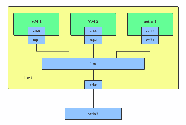
下面是一个是创建 Brdige 并连接其他网络设备的示例:
ip link add br0 type bridge
ip link set eth0 master br0
ip link set tap1 master br0
ip link set tap2 master br0
ip link set veth1 master br0
上面的例子将会创建一个名为 br0 的 Bridge 设备,并将两个 TAP 设备和一个 VETH 设备作为其从属设备。
Bond
The Linux bonding driver provides a method for aggregating multiple network interfaces into a single logical “bonded” interface. The behavior of the bonded interface depends on the mode; generally speaking, modes provide either hot standby or load balancing services.
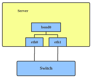
Use a bonded interface when you want to increase your link speed or do a failover on your server. Here’s how to create a bonded interface: ip link add bond1 type bond miimon 100 mode active-backup ip link set eth0 master bond1 ip link set eth1 master bond1 This creates a bonded interface named bond1 with mode active-backup. For other modes, please see the kernel documentation.
Team
Similar a bonded interface, the purpose of a team device is to provide a mechanism to group multiple NICs (ports) into one logical one (teamdev) at the L2 layer.
 The main thing to realize is that a team device is not trying to replicate or mimic a bonded interface. What it does is to solve the same problem using a different approach, using, for example, a lockless (RCU) TX/RX path and modular design.
But there are also some functional differences between a bonded interface and a team. For example, a team supports LACP load-balancing, NS/NA (IPV6) link monitoring, D-Bus interface, etc., which are absent in bonding. For further details about the differences between bonding and team, see Bonding vs. Team features.
Use a team when you want to use some features that bonding doesn’t provide.
Here’s how to create a team:
# teamd -o -n -U -d -t team0 -c ‘{“runner”: {“name”: “activebackup”},“link_watch”: {“name”: “ethtool”}}’ # ip link set eth0 down # ip link set eth1 down # teamdctl team0 port add eth0 # teamdctl team0 port add eth1
This creates a team interface named team0 with mode active-backup, and it adds eth0 and eth1 as team0’s sub-interfaces.
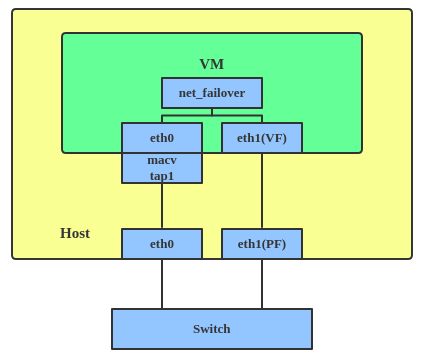
A new driver called net_failover has been added to Linux recently. It’s another failover master net device for virtualization and manages a primary (passthru/VF [Virtual Function] device) slave net device and a standby (the original paravirtual interface) slave net device.
The main thing to realize is that a team device is not trying to replicate or mimic a bonded interface. What it does is to solve the same problem using a different approach, using, for example, a lockless (RCU) TX/RX path and modular design.
But there are also some functional differences between a bonded interface and a team. For example, a team supports LACP load-balancing, NS/NA (IPV6) link monitoring, D-Bus interface, etc., which are absent in bonding. For further details about the differences between bonding and team, see Bonding vs. Team features.
Use a team when you want to use some features that bonding doesn’t provide.
Here’s how to create a team:
# teamd -o -n -U -d -t team0 -c ‘{“runner”: {“name”: “activebackup”},“link_watch”: {“name”: “ethtool”}}’ # ip link set eth0 down # ip link set eth1 down # teamdctl team0 port add eth0 # teamdctl team0 port add eth1
This creates a team interface named team0 with mode active-backup, and it adds eth0 and eth1 as team0’s sub-interfaces.
A new driver called net_failover has been added to Linux recently. It’s another failover master net device for virtualization and manages a primary (passthru/VF [Virtual Function] device) slave net device and a standby (the original paravirtual interface) slave net device.
VLAN
A VLAN, aka virtual LAN, separates broadcast domains by adding tags to network packets. VLANs allow network administrators to group hosts under the same switch or between different switches.
The VLAN header looks like:
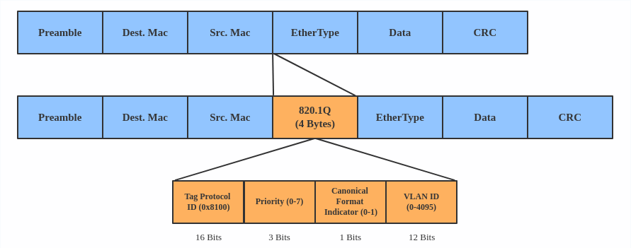 Use a VLAN when you want to separate subnet in VMs, namespaces, or hosts.
Here’s how to create a VLAN:
# ip link add link eth0 name eth0.2 type vlan id 2 # ip link add link eth0 name eth0.3 type vlan id 3
This adds VLAN 2 with name eth0.2 and VLAN 3 with name eth0.3. The topology looks like this:
Use a VLAN when you want to separate subnet in VMs, namespaces, or hosts.
Here’s how to create a VLAN:
# ip link add link eth0 name eth0.2 type vlan id 2 # ip link add link eth0 name eth0.3 type vlan id 3
This adds VLAN 2 with name eth0.2 and VLAN 3 with name eth0.3. The topology looks like this:
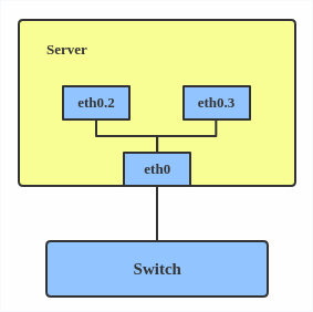 Note: When configuring a VLAN, you need to make sure the switch connected to the host is able to handle VLAN tags, for example, by setting the switch port to trunk mode.
VXLAN
VXLAN (Virtual eXtensible Local Area Network) is a tunneling protocol designed to solve the problem of limited VLAN IDs (4,096) in IEEE 802.1q. It is described by IETF RFC 7348.
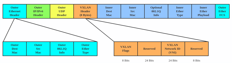
With a 24-bit segment ID, aka VXLAN Network Identifier (VNI), VXLAN allows up to 2^24 (16,777,216) virtual LANs, which is 4,096 times the VLAN capacity.
VXLAN encapsulates Layer 2 frames with a VXLAN header into a UDP-IP packet, which looks like this:
 VXLAN is typically deployed in data centers on virtualized hosts, which may be spread across multiple racks.
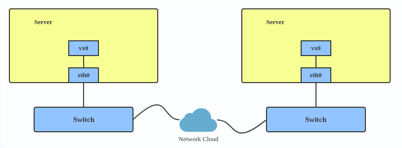 Here’s how to use VXLAN:
# ip link add vx0 type vxlan id 100 local 1.1.1.1 remote 2.2.2.2 dev eth0 dstport 4789
For reference, you can read the VXLAN kernel documentation or this VXLAN introduction.
Here’s how to use VXLAN:
# ip link add vx0 type vxlan id 100 local 1.1.1.1 remote 2.2.2.2 dev eth0 dstport 4789
For reference, you can read the VXLAN kernel documentation or this VXLAN introduction.
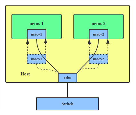
MACVLAN
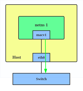
With VLAN, you can create multiple interfaces on top of a single one and filter packages based on a VLAN tag. With MACVLAN, you can create multiple interfaces with different Layer 2 (that is, Ethernet MAC) addresses on top of a single one.
Before MACVLAN, if you wanted to connect to physical network from a VM or namespace, you would have needed to create TAP/VETH devices and attach one side to a bridge and attach a physical interface to the bridge on the host at the same time, as shown below.
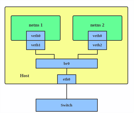 Now, with MACVLAN, you can bind a physical interface that is associated with a MACVLAN directly to namespaces, without the need for a bridge.
 There are five MACVLAN types:
1. Private: doesn’t allow communication between MACVLAN instances on the same physical interface, even if the external switch supports hairpin mode.
There are five MACVLAN types:
1. Private: doesn’t allow communication between MACVLAN instances on the same physical interface, even if the external switch supports hairpin mode.
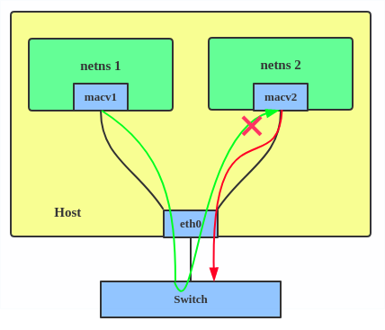 2. VEPA: data from one MACVLAN instance to the other on the same physical interface is transmitted over the physical interface. Either the attached switch needs to support hairpin mode or there must be a TCP/IP router forwarding the packets in order to allow communication.
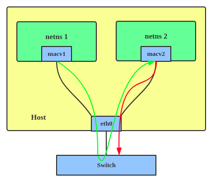 3. Bridge: all endpoints are directly connected to each other with a simple bridge via the physical interface.
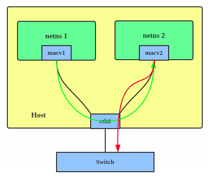 4. Passthru: allows a single VM to be connected directly to the physical interface.
 5. Source: the source mode is used to filter traffic based on a list of allowed source MAC addresses to create MAC-based VLAN associations. Please see the commit message.
The type is chosen according to different needs. Bridge mode is the most commonly used.
Use a MACVLAN when you want to connect directly to a physical network from containers.
Here’s how to set up a MACVLAN:
# ip link add macvlan1 link eth0 type macvlan mode bridge # ip link add macvlan2 link eth0 type macvlan mode bridge # ip netns add net1 # ip netns add net2 # ip link set macvlan1 netns net1 # ip link set macvlan2 netns net2
This creates two new MACVLAN devices in bridge mode and assigns these two devices to two different namespaces.
5. Source: the source mode is used to filter traffic based on a list of allowed source MAC addresses to create MAC-based VLAN associations. Please see the commit message.
The type is chosen according to different needs. Bridge mode is the most commonly used.
Use a MACVLAN when you want to connect directly to a physical network from containers.
Here’s how to set up a MACVLAN:
# ip link add macvlan1 link eth0 type macvlan mode bridge # ip link add macvlan2 link eth0 type macvlan mode bridge # ip netns add net1 # ip netns add net2 # ip link set macvlan1 netns net1 # ip link set macvlan2 netns net2
This creates two new MACVLAN devices in bridge mode and assigns these two devices to two different namespaces.
IPVLAN
IPVLAN is similar to MACVLAN with the difference being that the endpoints have the same MAC address.
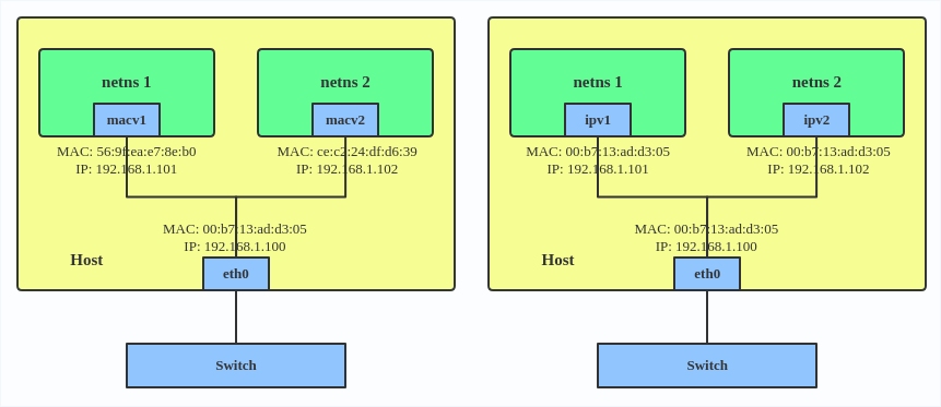 IPVLAN supports L2 and L3 mode. IPVLAN L2 mode acts like a MACVLAN in bridge mode. The parent interface looks like a bridge or switch.
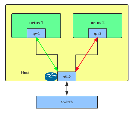
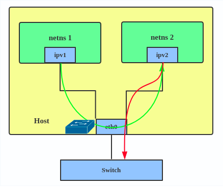 In IPVLAN L3 mode, the parent interface acts like a router and packets are routed between endpoints, which gives better scalability.
 Regarding when to use an IPVLAN, the IPVLAN kernel documentation says that MACVLAN and IPVLAN “are very similar in many regards and the specific use case could very well define which device to choose. if one of the following situations defines your use case then you can choose to use ipvlan -
(a) The Linux host that is connected to the external switch / router has policy configured that allows only one mac per port.
(b) No of virtual devices created on a master exceed the mac capacity and puts the NIC in promiscuous mode and degraded performance is a concern.
(c) If the slave device is to be put into the hostile / untrusted network namespace where L2 on the slave could be changed / misused.”
Here’s how to set up an IPVLAN instance:
# ip netns add ns0 # ip link add name ipvl0 link eth0 type ipvlan mode l2 # ip link set dev ipvl0 netns ns0
This creates an IPVLAN device named ipvl0 with mode L2, assigned to namespace ns0.
Regarding when to use an IPVLAN, the IPVLAN kernel documentation says that MACVLAN and IPVLAN “are very similar in many regards and the specific use case could very well define which device to choose. if one of the following situations defines your use case then you can choose to use ipvlan -
(a) The Linux host that is connected to the external switch / router has policy configured that allows only one mac per port.
(b) No of virtual devices created on a master exceed the mac capacity and puts the NIC in promiscuous mode and degraded performance is a concern.
(c) If the slave device is to be put into the hostile / untrusted network namespace where L2 on the slave could be changed / misused.”
Here’s how to set up an IPVLAN instance:
# ip netns add ns0 # ip link add name ipvl0 link eth0 type ipvlan mode l2 # ip link set dev ipvl0 netns ns0
This creates an IPVLAN device named ipvl0 with mode L2, assigned to namespace ns0.
MACVTAP/IPVTAP
MACVTAP/IPVTAP is a new device driver meant to simplify virtualized bridged networking. When a MACVTAP/IPVTAP instance is created on top of a physical interface, the kernel also creates a character device/dev/tapX to be used just like a TUN/TAP device, which can be directly used by KVM/QEMU.
With MACVTAP/IPVTAP, you can replace the combination of TUN/TAP and bridge drivers with a single module:
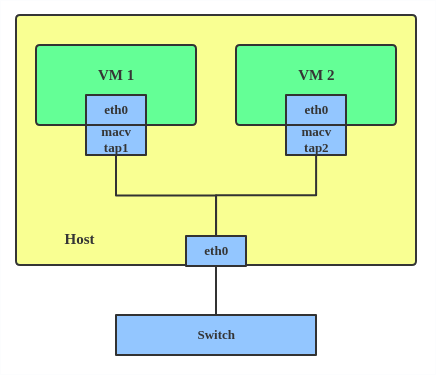 Typically, MACVLAN/IPVLAN is used to make both the guest and the host show up directly on the switch to which the host is connected. The difference between MACVTAP and IPVTAP is same as with MACVLAN/IPVLAN.
Here’s how to create a MACVTAP instance:
# ip link add link eth0 name macvtap0 type macvtap
Typically, MACVLAN/IPVLAN is used to make both the guest and the host show up directly on the switch to which the host is connected. The difference between MACVTAP and IPVTAP is same as with MACVLAN/IPVLAN.
Here’s how to create a MACVTAP instance:
# ip link add link eth0 name macvtap0 type macvtap
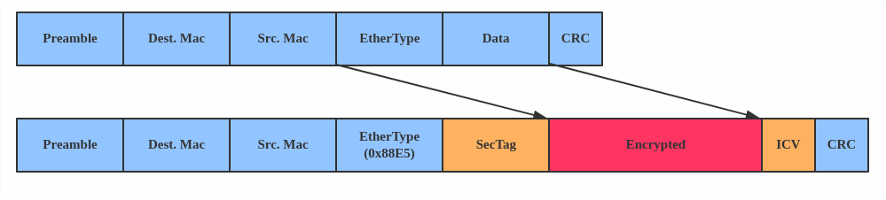
MACsec
MACsec (Media Access Control Security) is an IEEE standard for security in wired Ethernet LANs. Similar to IPsec, as a layer 2 specification, MACsec can protect not only IP traffic but also ARP, neighbor discovery, and DHCP. The MACsec headers look like this:
 The main use case for MACsec is to secure all messages on a standard LAN including ARP, NS, and DHCP messages.
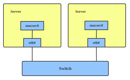 Here’s how to set up a MACsec configuration:
# ip link add macsec0 link eth1 type macsec
Note: This only adds a MACsec device called macsec0 on interface eth1. For more detailed configurations, please see the “Configuration example” section in this MACsec introduction by Sabrina Dubroca.
Here’s how to set up a MACsec configuration:
# ip link add macsec0 link eth1 type macsec
Note: This only adds a MACsec device called macsec0 on interface eth1. For more detailed configurations, please see the “Configuration example” section in this MACsec introduction by Sabrina Dubroca.
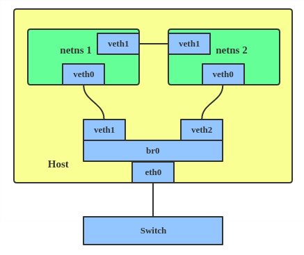
VETH
The VETH (virtual Ethernet) device is a local Ethernet tunnel. Devices are created in pairs, as shown in the diagram below.
Packets transmitted on one device in the pair are immediately received on the other device. When either device is down, the link state of the pair is down.
 Use a VETH configuration when namespaces need to communicate to the main host namespace or between each other.
Here’s how to set up a VETH configuration:
# ip netns add net1 # ip netns add net2 # ip link add veth1 netns net1 type veth peer name veth2 netns net2
This creates two namespaces, net1 and net2, and a pair of VETH devices, and it assigns veth1 to namespace net1 and veth2 to namespace net2. These two namespaces are connected with this VETH pair. Assign a pair of IP addresses, and you can ping and communicate between the two namespaces.
Use a VETH configuration when namespaces need to communicate to the main host namespace or between each other.
Here’s how to set up a VETH configuration:
# ip netns add net1 # ip netns add net2 # ip link add veth1 netns net1 type veth peer name veth2 netns net2
This creates two namespaces, net1 and net2, and a pair of VETH devices, and it assigns veth1 to namespace net1 and veth2 to namespace net2. These two namespaces are connected with this VETH pair. Assign a pair of IP addresses, and you can ping and communicate between the two namespaces.
VCAN
Similar to the network loopback devices, the VCAN (virtual CAN) driver offers a virtual local CAN (Controller Area Network) interface, so users can send/receive CAN messages via a VCAN interface. CAN is mostly used in the automotive field nowadays. For more CAN protocol information, please refer to the kernel CAN documentation. Use a VCAN when you want to test a CAN protocol implementation on the local host. Here’s how to create a VCAN: # ip link add dev vcan1 type vcan
VXCAN
Similar to the VETH driver, a VXCAN (Virtual CAN tunnel) implements a local CAN traffic tunnel between two VCAN network devices. When you create a VXCAN instance, two VXCAN devices are created as a pair. When one end receives the packet, the packet appears on the device’s pair and vice versa. VXCAN can be used for cross-namespace communication. Use a VXCAN configuration when you want to send CAN message across namespaces. Here’s how to set up a VXCAN instance: # ip netns add net1 # ip netns add net2 # ip link add vxcan1 netns net1 type vxcan peer name vxcan2 netns net2 Note: VXCAN is not yet supported in Red Hat Enterprise Linux.
IPOIB
An IPOIB device supports the IP-over-InfiniBand protocol. This transports IP packets over InfiniBand (IB) so you can use your IB device as a fast NIC. The IPoIB driver supports two modes of operation: datagram and connected. In datagram mode, the IB UD (Unreliable Datagram) transport is used. In connected mode, the IB RC (Reliable Connected) transport is used. The connected mode takes advantage of the connected nature of the IB transport and allows an MTU up to the maximal IP packet size of 64K. For more details, please see the IPOIB kernel documentation. Use an IPOIB device when you have an IB device and want to communicate with a remote host via IP. Here’s how to create an IPOIB device: # ip link add ib0 name ipoib0 type ipoib pkey IB_PKEY mode connected
NLMON
NLMON is a Netlink monitor device. Use an NLMON device when you want to monitor system Netlink messages. Here’s how to create an NLMON device: # ip link add nlmon0 type nlmon # ip link set nlmon0 up # tcpdump -i nlmon0 -w nlmsg.pcap This creates an NLMON device named nlmon0 and sets it up. Use a packet sniffer (for example, tcpdump) to capture Netlink messages. Recent versions of Wireshark feature decoding of Netlink messages.
Dummy
dummy 是一个网络接口,是完全虚拟的,就像 loopback 设备。dummy 设备的目的是提供一种网络设备,用以路由数据包,而无需实际传输他们
使用 dummy 设备使不活动的 SLIP(串行线路 Internet 协议) 地址看起来像本地程序的真实地址。 现在,dummy 设备主要用于测试和调试,同时,在 Kubernetes 中,Flannel 在 ipvs 模式下,也会创建一个名为 kube-ipvs0 的网络设备来路由数据包。
dummy 设备的创建方式如下:
ip link add dummy1 type dummy
ip addr add 1.1.1.1/24 dev dummy1
ip link set dummy1 up
IFB
The IFB (Intermediate Functional Block) driver supplies a device that allows the concentration of traffic from several sources and the shaping incoming traffic instead of dropping it. Use an IFB interface when you want to queue and shape incoming traffic. Here’s how to create an IFB interface: # ip link add ifb0 type ifb # ip link set ifb0 up # tc qdisc add dev ifb0 root sfq # tc qdisc add dev eth0 handle ffff: ingress # tc filter add dev eth0 parent ffff: u32 match u32 0 0 action mirred egress redirect dev ifb0 This creates an IFB device named ifb0 and replaces the root qdisc scheduler with SFQ (Stochastic Fairness Queueing), which is a classless queueing scheduler. Then it adds an ingress qdisc scheduler on eth0 and redirects all ingress traffic to ifb0. For more IFB qdisc use cases, please refer to this Linux Foundation wiki on IFB.
Additional resources
- Virtual networking articles on the Red Hat Developer blog
- Dynamic IP Address Management in Open Virtual Network (OVN)
- Non-root Open vSwitch in Red Hat Enterprise Linux
- Open vSwitch articles on the Red hat Developer Blog
netdevsim interface
netdevsim is a simulated networking device which is used for testing various networking APIs. At this time it is particularly focused on testing hardware offloading, tc/XDP BPF and SR-IOV. A netdevsim device can be created as follows # ip link add dev sim0 type netdevsim # ip link set dev sim0 up To enable tc offload: # ethtool -K sim0 hw-tc-offload on To load XDP BPF or tc BPF programs: # ip link set dev sim0 xdpoffload obj prog.o To add VFs for SR-IOV testing: # echo 3 > /sys/class/net/sim0/device/sriovnumvfs # ip link set sim0 vf 0 mac To change the vf numbers, you need to disable them completely first: # echo 0 > /sys/class/net/sim0/device/sriov_numvfs # echo 5 > /sys/class/net/sim0/device/sriov_numvfs Note: netdevsim is not compiled in RHEL by default _Last updated: September 11, 2019
隧道网络设备
参考:
Linux 支持多种隧道,但新用户可能会对它们的差异感到困惑,并不确定哪一种最适合给定的用例。在本文中,我将简要介绍 Linux 内核中常用的隧道接口。没有代码分析,只简单介绍了接口及其在 Linux 上的使用。任何有网络背景的人都可能对这些信息感兴趣。可以通过发出 iproute2 命令 ip link help 获得隧道接口列表以及特定隧道配置的帮助。
这篇文章涵盖了以下常用接口:
- IPIP Tunnel
- SIT Tunnel
- ip6tnl Tunnel
- VTI and VTI6
- GRE and GRETAP
- IP6GRE and IP6GRETAP
- FOU
- GUE
- GENEVE
- ERSPAN and IP6ERSPAN
IPIP Tunnel
IPIP tunnel, just as the name suggests, is an IP over IP tunnel, defined in RFC 2003. The IPIP tunnel header looks like:

It’s typically used to connect two internal IPv4 subnets through public IPv4 internet. It has the lowest overhead but can only transmit IPv4 unicast traffic. That means you cannot send multicast via IPIP tunnel. IPIP tunnel supports both IP over IP and MPLS over IP. Note: When the ipip module is loaded, or an IPIP device is created for the first time, the Linux kernel will create a tunl0 default device in each namespace, with attributes local=any and remote=any. When receiving IPIP protocol packets, the kernel will forward them to tunl0 as a fallback device if it can’t find another device whose local/remote attributes match their source or destination address more closely. Here is how to create an IPIP tunnel: On Server A: # ip link add name ipip0 type ipip local LOCAL_IPv4_ADDR remote REMOTE_IPv4_ADDR # ip link set ipip0 up # ip addr add INTERNAL_IPV4_ADDR/24 dev ipip0 Add a remote internal subnet route if the endpoints don’t belong to the same subnet # ip route add REMOTE_INTERNAL_SUBNET/24 dev ipip0 On Server B: # ip link add name ipip0 type ipip local LOCAL_IPv4_ADDR remote REMOTE_IPv4_ADDR # ip link set ipip0 up # ip addr add INTERNAL_IPV4_ADDR/24 dev ipip0 # ip route add REMOTE_INTERNAL_SUBNET/24 dev ipip0 Note: Please replace LOCAL_IPv4_ADDR, REMOTE_IPv4_ADDR, INTERNAL_IPV4_ADDR, REMOTE_INTERNAL_SUBNET to the addresses based on your testing environment. The same with following example configs.
SIT Tunnel
SIT stands for Simple Internet Transition. The main purpose is to interconnect isolated IPv6 networks, located in global IPv4 internet.
Initially, it only had an IPv6 over IPv4 tunneling mode. After years of development, however, it acquired support for several different modes, such as ipip (the same with IPIP tunnel), ip6ip, mplsip, and any. Mode any is used to accept both IP and IPv6 traffic, which may prove useful in some deployments. SIT tunnel also supports ISATA, and here is a usage example.
The SIT tunnel header looks like:
 When the sit module is loaded, the Linux kernel will create a default device, named sit0.
Here is how to create a SIT tunnel:
On Server A: # ip link add name sit1 type sit local LOCAL_IPv4_ADDR remote REMOTE_IPv4_ADDR mode any # ip link set sit1 up # ip addr add INTERNAL_IPV4_ADDR/24 dev sit1
Then, perform the same steps on the remote side.
When the sit module is loaded, the Linux kernel will create a default device, named sit0.
Here is how to create a SIT tunnel:
On Server A: # ip link add name sit1 type sit local LOCAL_IPv4_ADDR remote REMOTE_IPv4_ADDR mode any # ip link set sit1 up # ip addr add INTERNAL_IPV4_ADDR/24 dev sit1
Then, perform the same steps on the remote side.
ip6tnl Tunnel
ip6tnl is an IPv4/IPv6 over IPv6 tunnel interface, which looks like an IPv6 version of the SIT tunnel. The tunnel header looks like:
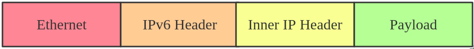 ip6tnl supports modes ip6ip6, ipip6, any. Mode ipip6 is IPv4 over IPv6, and mode ip6ip6 is IPv6 over IPv6, and mode any supports both IPv4/IPv6 over IPv6.
When the ip6tnl module is loaded, the Linux kernel will create a default device, named ip6tnl0.
Here is how to create an ip6tnl tunnel:
# ip link add name ipip6 type ip6tnl local LOCAL_IPv6_ADDR remote REMOTE_IPv6_ADDR mode any
ip6tnl supports modes ip6ip6, ipip6, any. Mode ipip6 is IPv4 over IPv6, and mode ip6ip6 is IPv6 over IPv6, and mode any supports both IPv4/IPv6 over IPv6.
When the ip6tnl module is loaded, the Linux kernel will create a default device, named ip6tnl0.
Here is how to create an ip6tnl tunnel:
# ip link add name ipip6 type ip6tnl local LOCAL_IPv6_ADDR remote REMOTE_IPv6_ADDR mode any
VTI and VTI6
Virtual Tunnel Interface (VTI) on Linux is similar to Cisco’s VTI and Juniper’s implementation of secure tunnel (st.xx). This particular tunneling driver implements IP encapsulations, which can be used with xfrm to give the notion of a secure tunnel and then use kernel routing on top. In general, VTI tunnels operate in almost the same way as ipip or sit tunnels, except that they add a fwmark and IPsec encapsulation/decapsulation. VTI6 is the IPv6 equivalent of VTI. Here is how to create a VTI tunnel: # ip link add name vti1 type vti key VTI_KEY local LOCAL_IPv4_ADDR remote REMOTE_IPv4_ADDR # ip link set vti1 up # ip addr add LOCAL_VIRTUAL_ADDR/24 dev vti1 # ip xfrm state add src LOCAL_IPv4_ADDR dst REMOTE_IPv4_ADDR spi SPI PROTO ALGR mode tunnel # ip xfrm state add src REMOTE_IPv4_ADDR dst LOCAL_IPv4_ADDR spi SPI PROTO ALGR mode tunnel # ip xfrm policy add dir in tmpl src REMOTE_IPv4_ADDR dst LOCAL_IPv4_ADDR PROTO mode tunnel mark VTI_KEY # ip xfrm policy add dir out tmpl src LOCAL_IPv4_ADDR dst REMOTE_IPv4_ADDR PROTO mode tunnel mark VTI_KEY You can also configure IPsec via libreswan or strongSwan.
GRE and GRETAP
Generic Routing Encapsulation, also known as GRE, is defined in RFC 2784
GRE tunneling adds an additional GRE header between the inside and outside IP headers. In theory, GRE could encapsulate any Layer 3 protocol with a valid Ethernet type, unlike IPIP, which can only encapsulate IP. The GRE header looks like:
 Note that you can transport multicast traffic and IPv6 through a GRE tunnel.
When the gre module is loaded, the Linux kernel will create a default device, named gre0.
Here is how to create a GRE tunnel:
# ip link add name gre1 type gre local LOCAL_IPv4_ADDR remote REMOTE_IPv4_ADDR [seq] key KEY
While GRE tunnels operate at OSI Layer 3, GRETAP works at OSI Layer 2, which means there is an Ethernet header in the inner header.
Note that you can transport multicast traffic and IPv6 through a GRE tunnel.
When the gre module is loaded, the Linux kernel will create a default device, named gre0.
Here is how to create a GRE tunnel:
# ip link add name gre1 type gre local LOCAL_IPv4_ADDR remote REMOTE_IPv4_ADDR [seq] key KEY
While GRE tunnels operate at OSI Layer 3, GRETAP works at OSI Layer 2, which means there is an Ethernet header in the inner header.
 Here is how to create a GRETAP tunnel:
# ip link add name gretap1 type gretap local LOCAL_IPv4_ADDR remote REMOTE_IPv4_ADDR
Here is how to create a GRETAP tunnel:
# ip link add name gretap1 type gretap local LOCAL_IPv4_ADDR remote REMOTE_IPv4_ADDR
IP6GRE and IP6GRETAP
IP6GRE is the IPv6 equivalent of GRE, which allows us to encapsulate any Layer 3 protocol over IPv6. The tunnel header looks like:
 IP6GRETAP, just like GRETAP, has an Ethernet header in the inner header:
 Here is how to create a GRE tunnel:
# ip link add name gre1 type ip6gre local LOCAL_IPv6_ADDR remote REMOTE_IPv6_ADDR # ip link add name gretap1 type ip6gretap local LOCAL_IPv6_ADDR remote REMOTE_IPv6_ADDR
Here is how to create a GRE tunnel:
# ip link add name gre1 type ip6gre local LOCAL_IPv6_ADDR remote REMOTE_IPv6_ADDR # ip link add name gretap1 type ip6gretap local LOCAL_IPv6_ADDR remote REMOTE_IPv6_ADDR
FOU
Tunneling can happen at multiple levels in the networking stack. IPIP, SIT, GRE tunnels are at the IP level, while FOU (foo over UDP) is UDP-level tunneling.
There are some advantages of using UDP tunneling as UDP works with existing HW infrastructure, like RSS in NICs, ECMP in switches, and checksum offload. The developer’s patch set shows significant performance increases for the SIT and IPIP protocols.
Currently, the FOU tunnel supports encapsulation protocol based on IPIP, SIT, GRE. An example FOU header looks like:
 Here is how to create a FOU tunnel:
# ip fou add port 5555 ipproto 4 # ip link add name tun1 type ipip remote 192.168.1.1 local 192.168.1.2 ttl 225 encap fou encap-sport auto encap-dport 5555
The first command configured a FOU receive port for IPIP bound to 5555; for GRE, you need to set ipproto 47. The second command set up a new IPIP virtual interface (tun1) configured for FOU encapsulation, with dest port 5555.
NOTE: FOU is not supported in Red Hat Enterprise Linux.
Here is how to create a FOU tunnel:
# ip fou add port 5555 ipproto 4 # ip link add name tun1 type ipip remote 192.168.1.1 local 192.168.1.2 ttl 225 encap fou encap-sport auto encap-dport 5555
The first command configured a FOU receive port for IPIP bound to 5555; for GRE, you need to set ipproto 47. The second command set up a new IPIP virtual interface (tun1) configured for FOU encapsulation, with dest port 5555.
NOTE: FOU is not supported in Red Hat Enterprise Linux.
GUE
Generic UDP Encapsulation (GUE) is another kind of UDP tunneling. The difference between FOU and GUE is that GUE has its own encapsulation header, which contains the protocol info and other data.
Currently, GUE tunnel supports inner IPIP, SIT, GRE encapsulation. An example GUE header looks like:
 Here is how to create a GUE tunnel:
# ip fou add port 5555 gue # ip link add name tun1 type ipip remote 192.168.1.1 local 192.168.1.2 ttl 225 encap gue encap-sport auto encap-dport 5555
This will set up a GUE receive port for IPIP bound to 5555, and an IPIP tunnel configured for GUE encapsulation.
NOTE: GUE is not supported in Red Hat Enterprise Linux.
Here is how to create a GUE tunnel:
# ip fou add port 5555 gue # ip link add name tun1 type ipip remote 192.168.1.1 local 192.168.1.2 ttl 225 encap gue encap-sport auto encap-dport 5555
This will set up a GUE receive port for IPIP bound to 5555, and an IPIP tunnel configured for GUE encapsulation.
NOTE: GUE is not supported in Red Hat Enterprise Linux.
GENEVE
Generic Network Virtualization Encapsulation (GENEVE) supports all of the capabilities of VXLAN, NVGRE, and STT and was designed to overcome their perceived limitations. Many believe GENEVE could eventually replace these earlier formats entirely. The tunnel header looks like:
 which looks very similar to VXLAN. The main difference is that the GENEVE header is flexible. It’s very easy to add new features by extending the header with a new Type-Length-Value (TLV) field. For more details, you can see the latest geneve ietf draft or refer to this What is GENEVE? article.
Open Virtual Network (OVN) uses GENEVE as default encapsulation. Here is how to create a GENEVE tunnel:
# ip link add name geneve0 type geneve id VNI remote REMOTE_IPv4_ADDR
which looks very similar to VXLAN. The main difference is that the GENEVE header is flexible. It’s very easy to add new features by extending the header with a new Type-Length-Value (TLV) field. For more details, you can see the latest geneve ietf draft or refer to this What is GENEVE? article.
Open Virtual Network (OVN) uses GENEVE as default encapsulation. Here is how to create a GENEVE tunnel:
# ip link add name geneve0 type geneve id VNI remote REMOTE_IPv4_ADDR
ERSPAN and IP6ERSPAN
Encapsulated Remote Switched Port Analyzer (ERSPAN) uses GRE encapsulation to extend the basic port mirroring capability from Layer 2 to Layer 3, which allows the mirrored traffic to be sent through a routable IP network. The ERSPAN header looks like:
 The ERSPAN tunnel allows a Linux host to act as an ERSPAN traffic source and send the ERSPAN mirrored traffic to either a remote host or to an ERSPAN destination, which receives and parses the ERSPAN packets generated from Cisco or other ERSPAN-capable switches. This setup could be used to analyze, diagnose, and detect malicious traffic.
Linux currently supports most features of two ERSPAN versions: v1 (type II) and v2 (type III).
Here is how to create an ERSPAN tunnel:
# ip link add dev erspan1 type erspan local LOCAL_IPv4_ADDR remote REMOTE_IPv4_ADDR seq key KEY erspan_ver 1 erspan IDX or # ip link add dev erspan1 type erspan local LOCAL_IPv4_ADDR remote REMOTE_IPv4_ADDR seq key KEY erspan_ver 2 erspan_dir DIRECTION erspan_hwid HWID Add tc filter to monitor traffic # tc qdisc add dev MONITOR_DEV handle ffff: ingress # tc filter add dev MONITOR_DEV parent ffff: matchall skip_hw action mirred egress mirror dev erspan1
The ERSPAN tunnel allows a Linux host to act as an ERSPAN traffic source and send the ERSPAN mirrored traffic to either a remote host or to an ERSPAN destination, which receives and parses the ERSPAN packets generated from Cisco or other ERSPAN-capable switches. This setup could be used to analyze, diagnose, and detect malicious traffic.
Linux currently supports most features of two ERSPAN versions: v1 (type II) and v2 (type III).
Here is how to create an ERSPAN tunnel:
# ip link add dev erspan1 type erspan local LOCAL_IPv4_ADDR remote REMOTE_IPv4_ADDR seq key KEY erspan_ver 1 erspan IDX or # ip link add dev erspan1 type erspan local LOCAL_IPv4_ADDR remote REMOTE_IPv4_ADDR seq key KEY erspan_ver 2 erspan_dir DIRECTION erspan_hwid HWID Add tc filter to monitor traffic # tc qdisc add dev MONITOR_DEV handle ffff: ingress # tc filter add dev MONITOR_DEV parent ffff: matchall skip_hw action mirred egress mirror dev erspan1
Summary
Here is a summary of all the tunnels we introduced.
| Tunnel/Link Type | Outer Header | Encapsulate Header | Inner Header |
|---|---|---|---|
| ipip | IPv4 | None | IPv4 |
| sit | IPv4 | None | IPv4/IPv6 |
| ip6tnl | IPv6 | None | IPv4/IPv6 |
| vti | IPv4 | IPsec | IPv4 |
| vti6 | IPv6 | IPsec | IPv6 |
| gre | IPv4 | GRE | IPv4/IPv6 |
| gretap | IPv4 | GRE | Ether + IPv4/IPv6 |
| ip6gre | IPv6 | GRE | IPv4/IPv6 |
| ip6gretap | IPv6 | GRE | Ether + IPv4/IPv6 |
| fou | IPv4/IPv6 | UDP | IPv4/IPv6/GRE |
| gue | IPv4/IPv6 | UDP + GUE | IPv4/IPv6/GRE |
| geneve | IPv4/IPv6 | UDP + Geneve | Ether + IPv4/IPv6 |
| erspan | IPv4 | GRE + ERSPAN | IPv4/IPv6 |
| ip6erspan | IPv6 | GRE + ERSPAN | IPv4/IPv6 |
Note: All configurations in this tutorial are volatile and won’t survive to a server reboot. If you want to make the configuration persistent across reboots, please consider using a networking configuration daemon, such as NetworkManager, or distribution-specific mechanisms. _Also read: _Introduction to Linux interfaces for virtual networking Last updated: October 18, 2019
反馈
此页是否对你有帮助?
Glad to hear it! Please tell us how we can improve.
Sorry to hear that. Please tell us how we can improve.